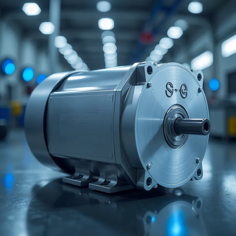
The MOSFET solution for the excitation motor is designed with a unique architecture that provides independent power supply for the armature and excitation winding. It focuses on three core requirements: wide speed range, strong overload resistance, and dual loop collaborative control. It covers the entire chain of armature H-bridge drive, excitation independent regulation, and energy feedback, and is suitable for heavy-duty scenarios such as industrial traction, electric forklifts, and high-power servos.
Dual winding independent drive core device scheme1. Armature main H-bridge drive linkAs the core of motor power output, the core requirements are high current breaking ability, low conduction loss, and the ability to cope with several times the peak current of starting and stalling:
High power overload solution: Infineon TLE4976-1K, 40V/209A, Rds (on) as low as 1.25m Ω under SGT process, TOLL package parasitic inductance extremely low, suitable for industrial traction separately excited motors under 10kW, device temperature rise controlled within 30K under locked rotor conditions
Mainstream industrial solution: VBM1606, 60V/120A, TO-220 package, SGT technology with Rds (on) of only 4m Ω, gate charge Qg of only 47nC, supporting 20kHz high-frequency PWM, suitable for conventional industrial servo separately excited motors under 5kW
High voltage power grid adaptation solution: VBPB18R47S, 800V/47A, TO-3P package, 90m Ω extremely low on resistance, compatible with 220V/380V industrial busbar, directly drives high-power metallurgical rolling mill separately excited motor
2. Independent control link of excitation windingAs the control core of speed regulation characteristics, the core requirements are wide range linear voltage regulation, fast demagnetization ability, and smooth transition of weak magnetic acceleration:
Precise control scheme: VBGQF1405, 40V/60A, DFN8 (3x3) package, with Rds (on) of only 4.2m Ω at 10V under SGT process, supporting stepless adjustment of 0-rated excitation current, and expanding the range of weak magnetic speed regulation to 1:100
Quick demagnetization solution: VBL18R17SE, 800V/17A, TO263 package, 280m Ω low on resistance, combined with freewheeling diode, can quickly demagnetize in fault state within 10ms, preventing motor runaway accidents
Low power excitation scheme: AO3401A, SOT-23 ultra small package, suitable for excitation control of 24V low-power separately excited servo. Only 1N4007 freewheeling diode needs to be connected in parallel to the periphery to completely suppress inductive load turn off spikes
3. Energy feedback and braking protection linkThe core requirements are bidirectional current carrying capacity, low body diode recovery loss, and efficient energy recharge during deceleration process:
Feedback preferred solution: Ansenmei FDP036N10A, 100V/120A, TO-220 package, 3.2m Ω low on resistance, conduction loss of only 18W at 75A current, excellent soft recovery characteristics of body diode, energy feedback efficiency improved to over 92%
Emergency braking plan: VBL2603, -60V/-130A, P-channel Trench process, Rds (on) as low as 3m Ω, sufficient redundancy for high current on/off capability, ensuring millisecond level activation of the energy consuming braking circuit and achieving rapid shutdown

 17374646018




 Follow
 17374646018
 E-mail
